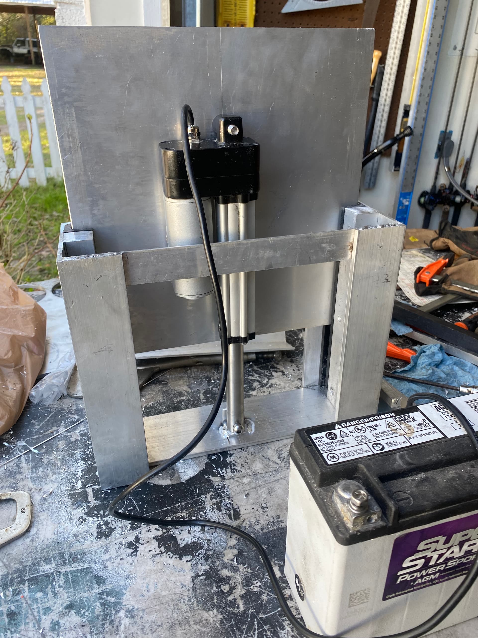
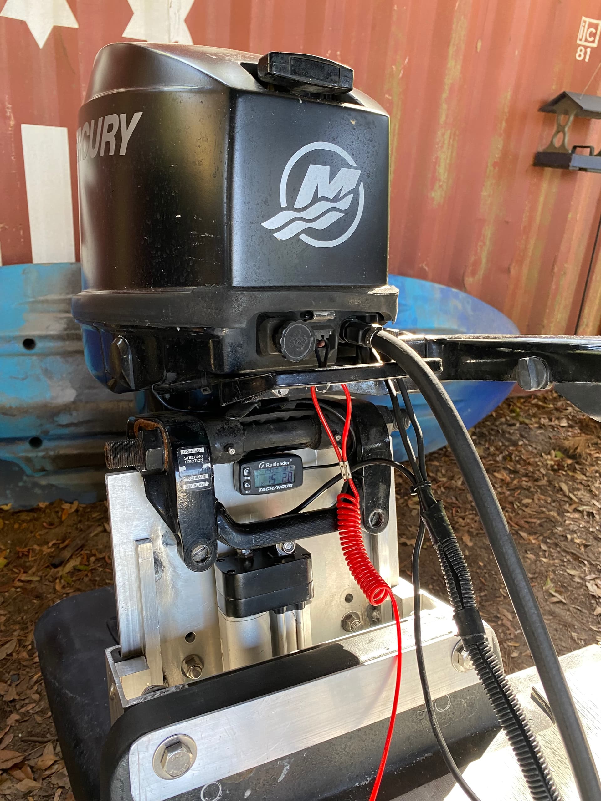
Here was a recent Jackplate build I did. I had a spare actuator laying around and figured I’d put it use. This particular actuator is a 4” linear actuator from progressive automations, and is the same actuator OTF jackplates uses. It quiet, doesn’t draw a lot of amps has a small profile, and comes in different lengths. The trade off is speed. It’s slow. The way I use it, the speed doesn’t really bother me much. Design wise, the last plate I built used stainless rods and guides, and a lot of bolts. It was smooth and robust, but used a lot of fasteners and was a pain to get everything lined up and bolted together, so I figured go a different route with this one. I’ve been running for a few months now and so far so good.
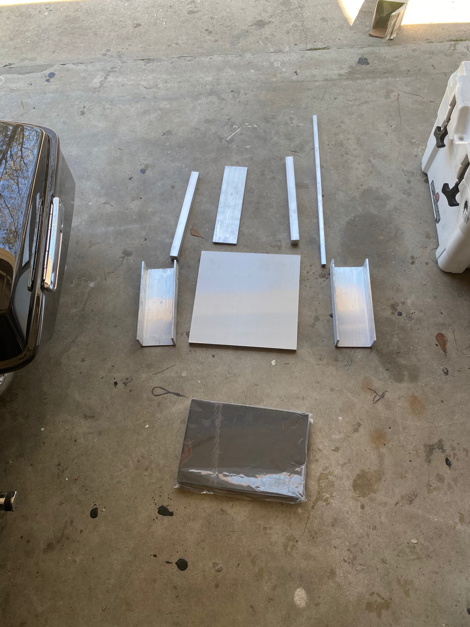
Here’s all the materials. 4” Alum channel, 1/2” alum plate, 1” Alum bar stock, 1/2” bar stock 1” starboard, 2”x 1/4” flat bar.
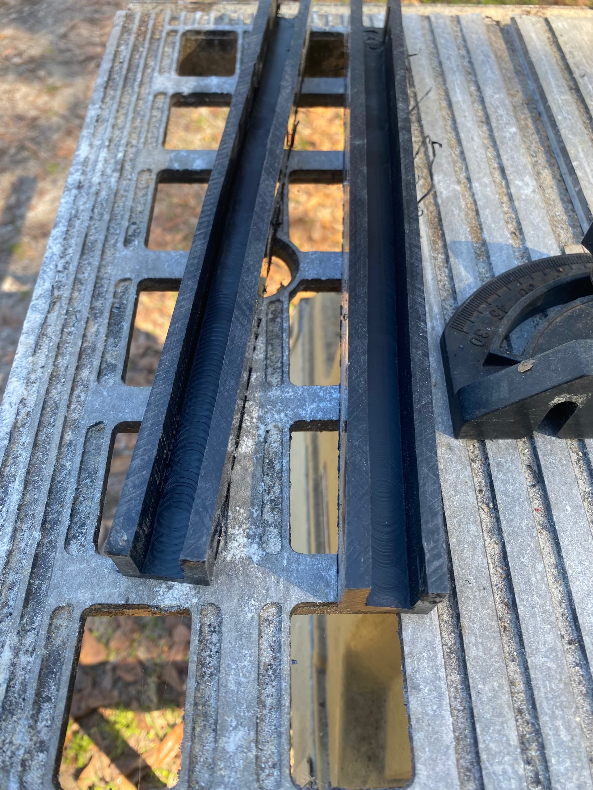
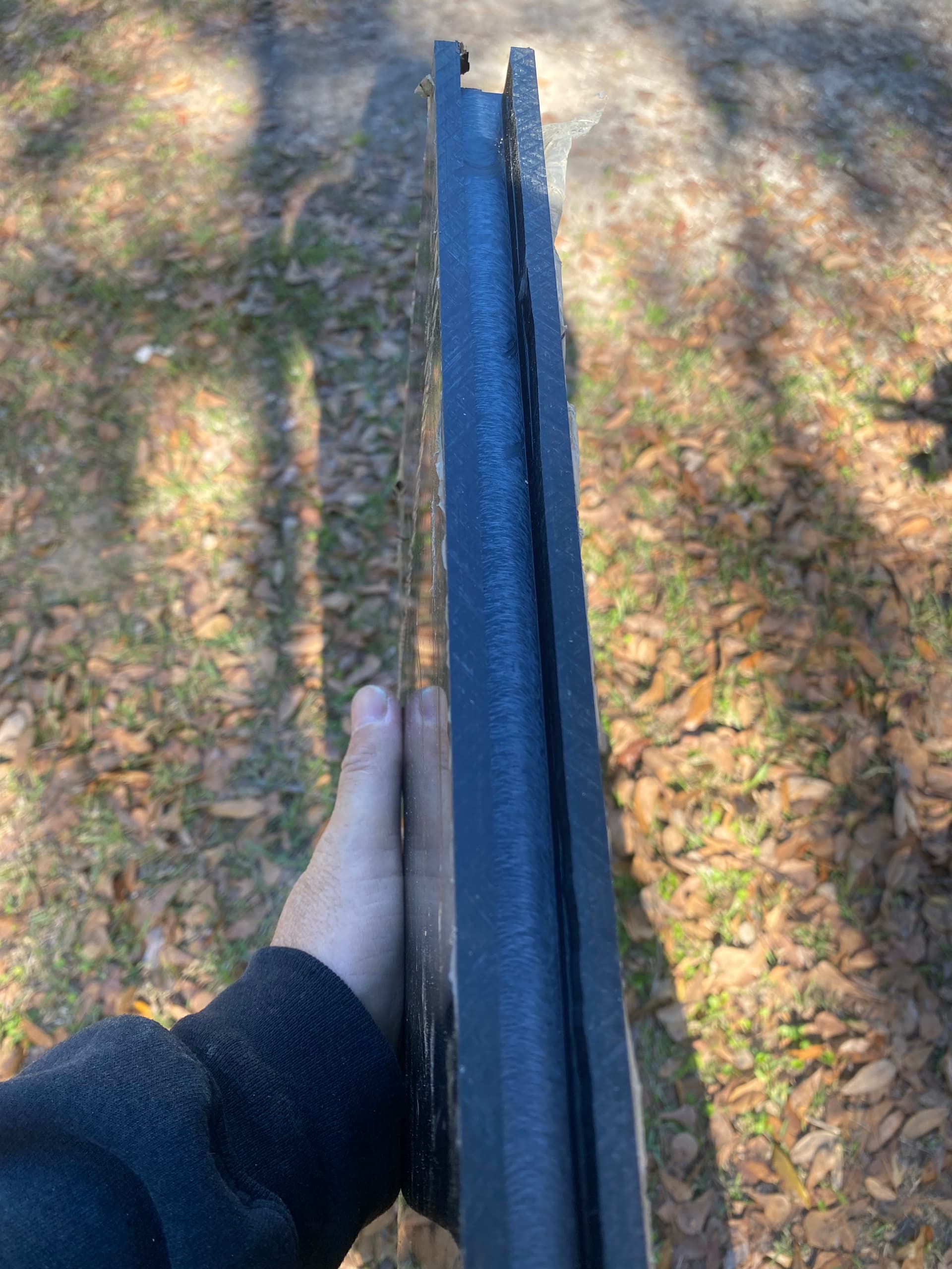
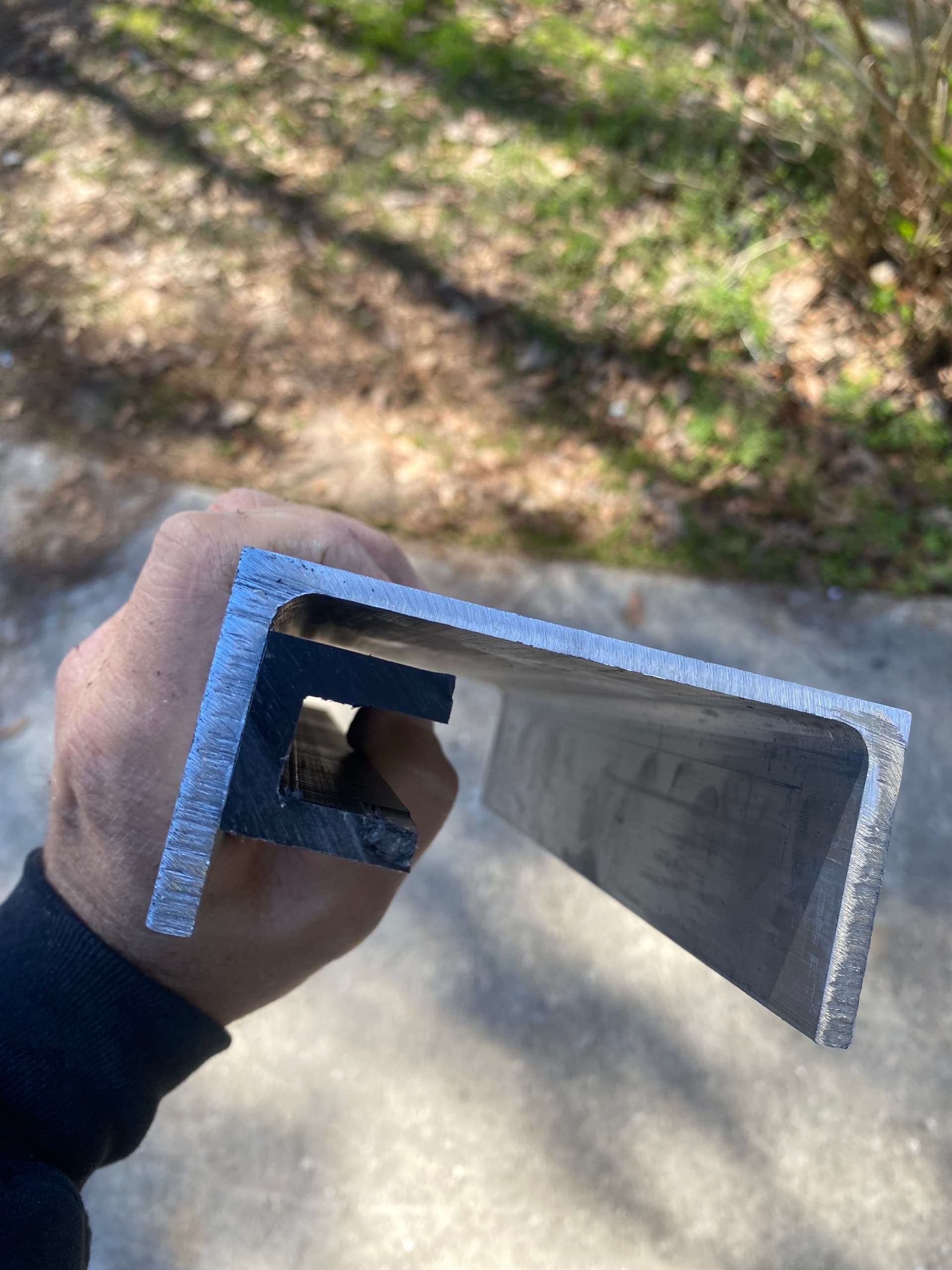
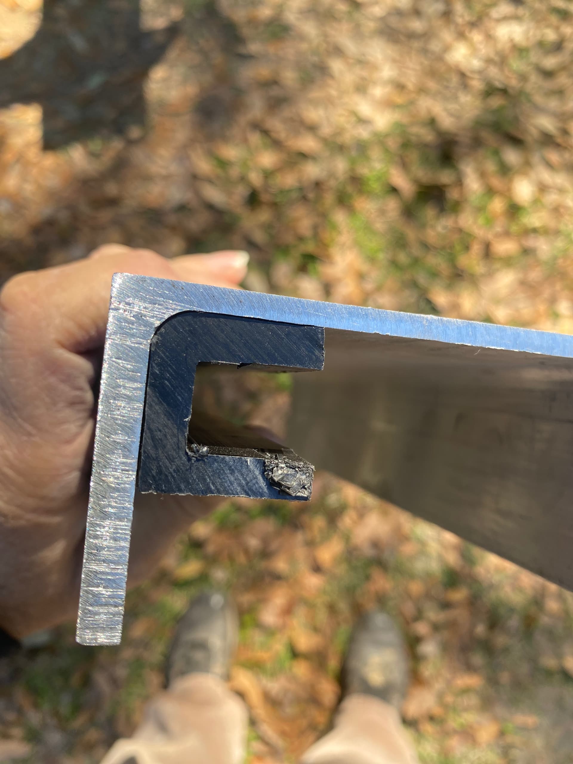
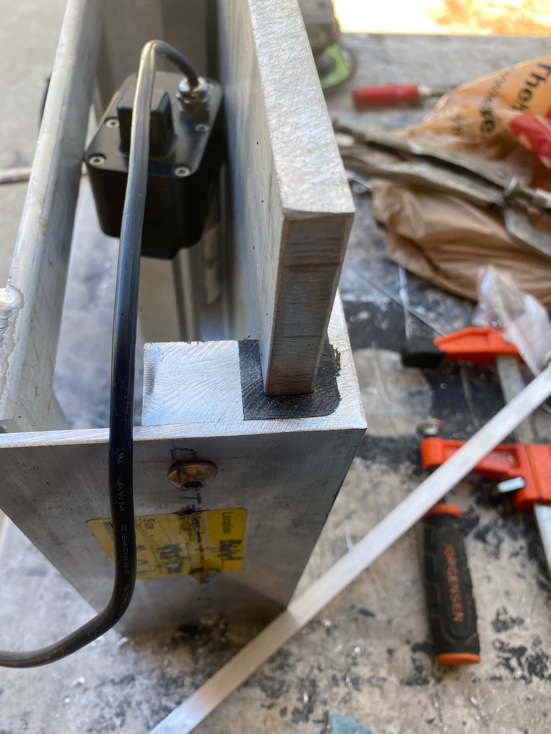
First up is fitting the starboard guides. 1/2” router bit for the plate to fit into, and round off the corners with a different router bit.
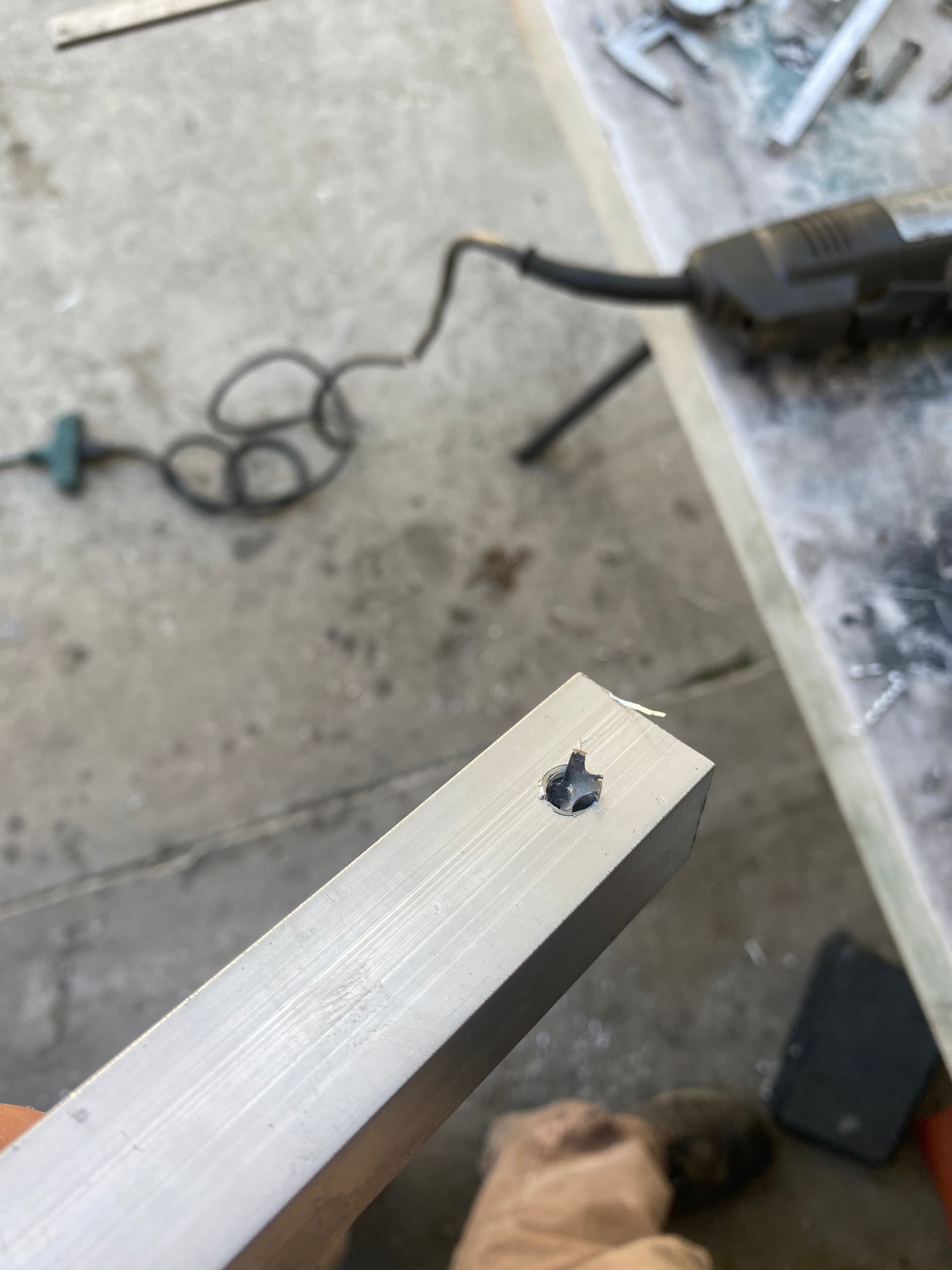
Then it’s on to drilling/tapping bolt holes in the 1” bar stock. This adds the strength to starboard guides. The other bar stock is welded, or could be bolted to the engine plate, to keep it from rocking side to side when lifting of lowering.
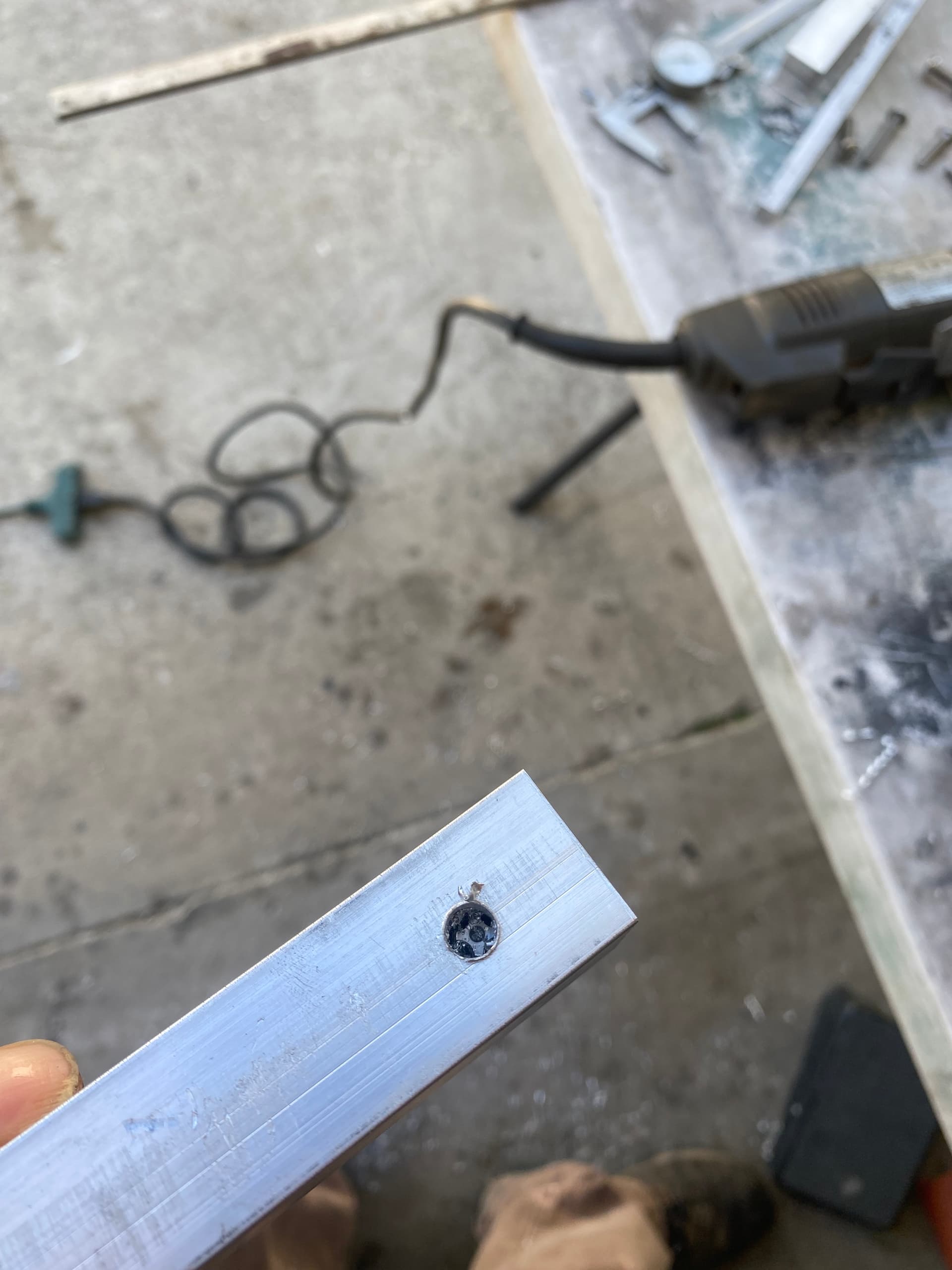
Of course tapping threads never seems to go to plan, and after 20years of doing so, my Snap on tap decided it’d had enough.
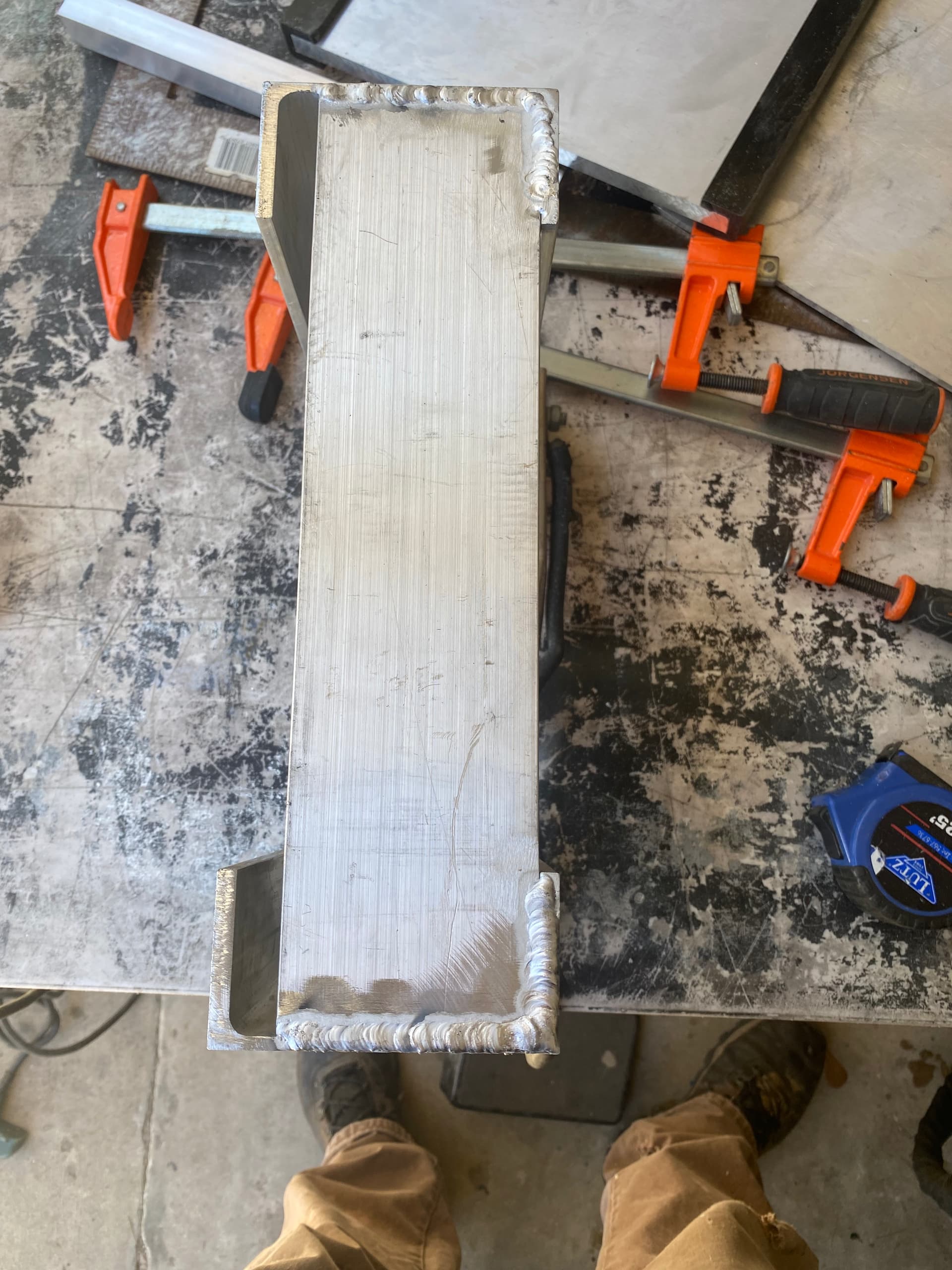
Also rounded off the corners on the bottom plate that will support the actuator. Here, if you were using a heavier engine, you’d likely want to upsize this plate or use a piece of Angle for added strength, but for my 120lb 2 smoker, the 1/4” flat bar is holding up fine.
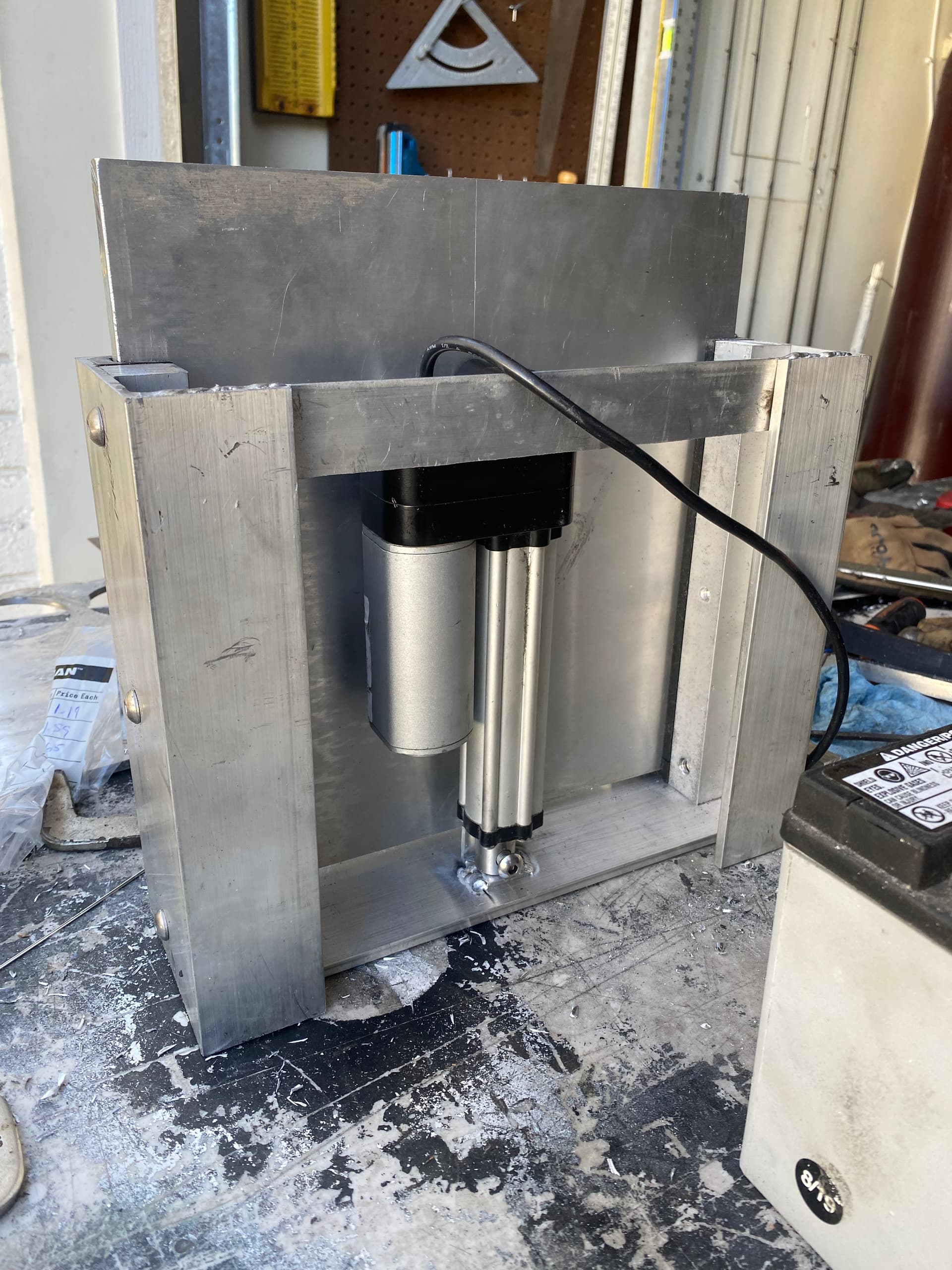
Welding another flat bar across the top just keeps everything together and square.
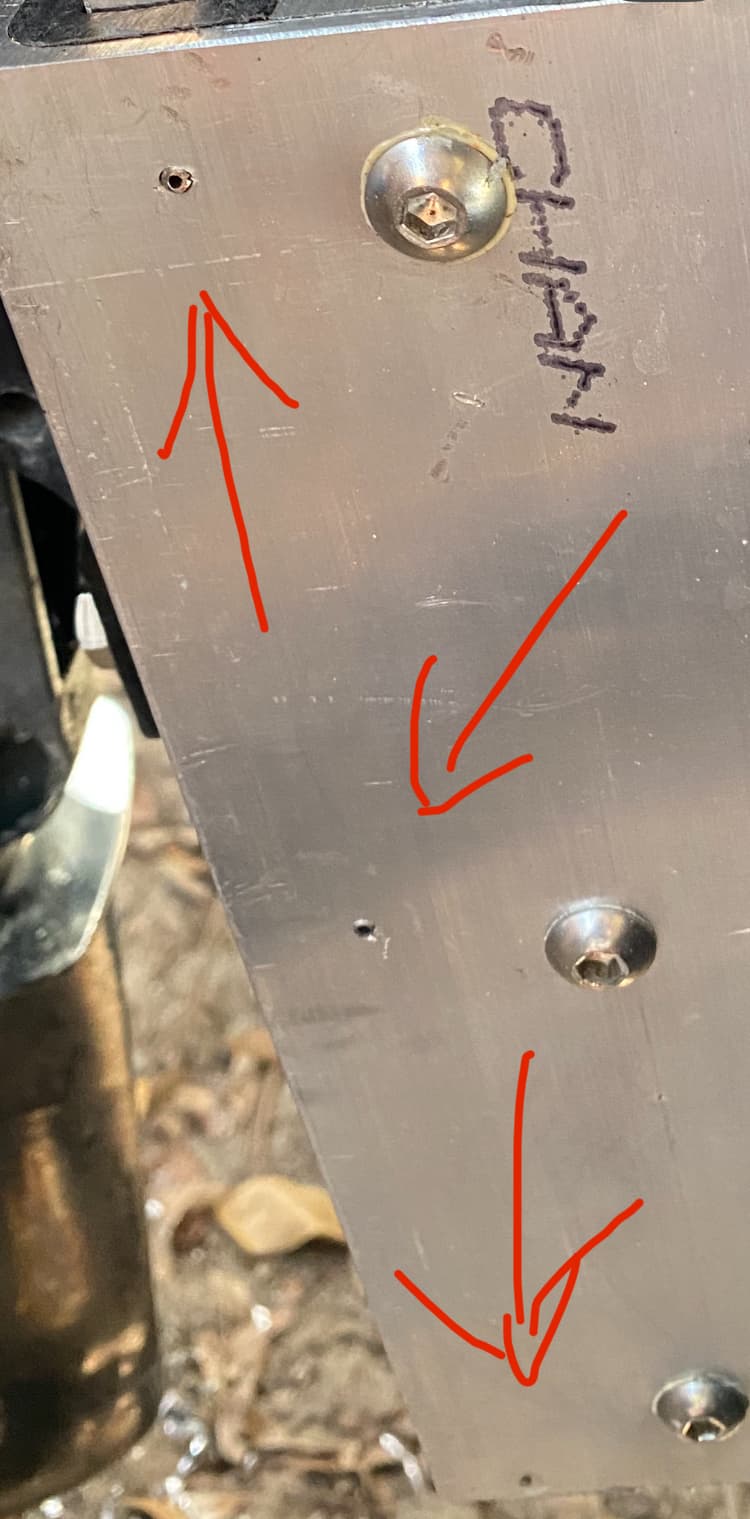
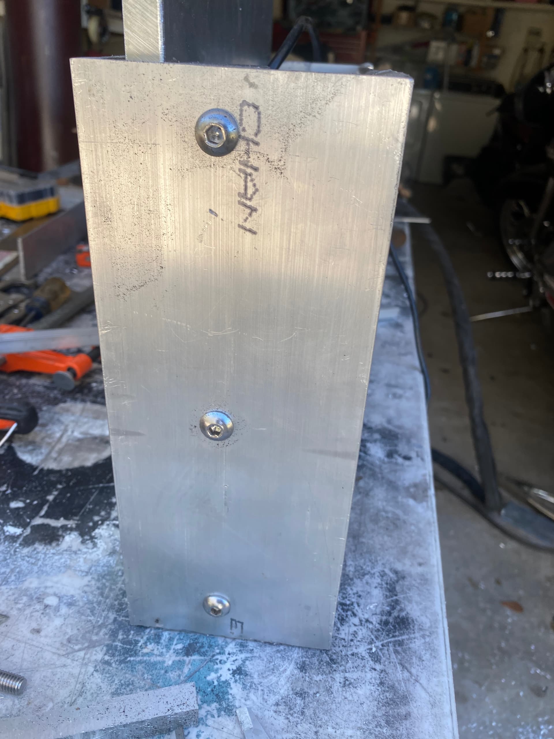
To keep the tracks in place, I drilled a couple small holes and inserted some stainless roll pins.
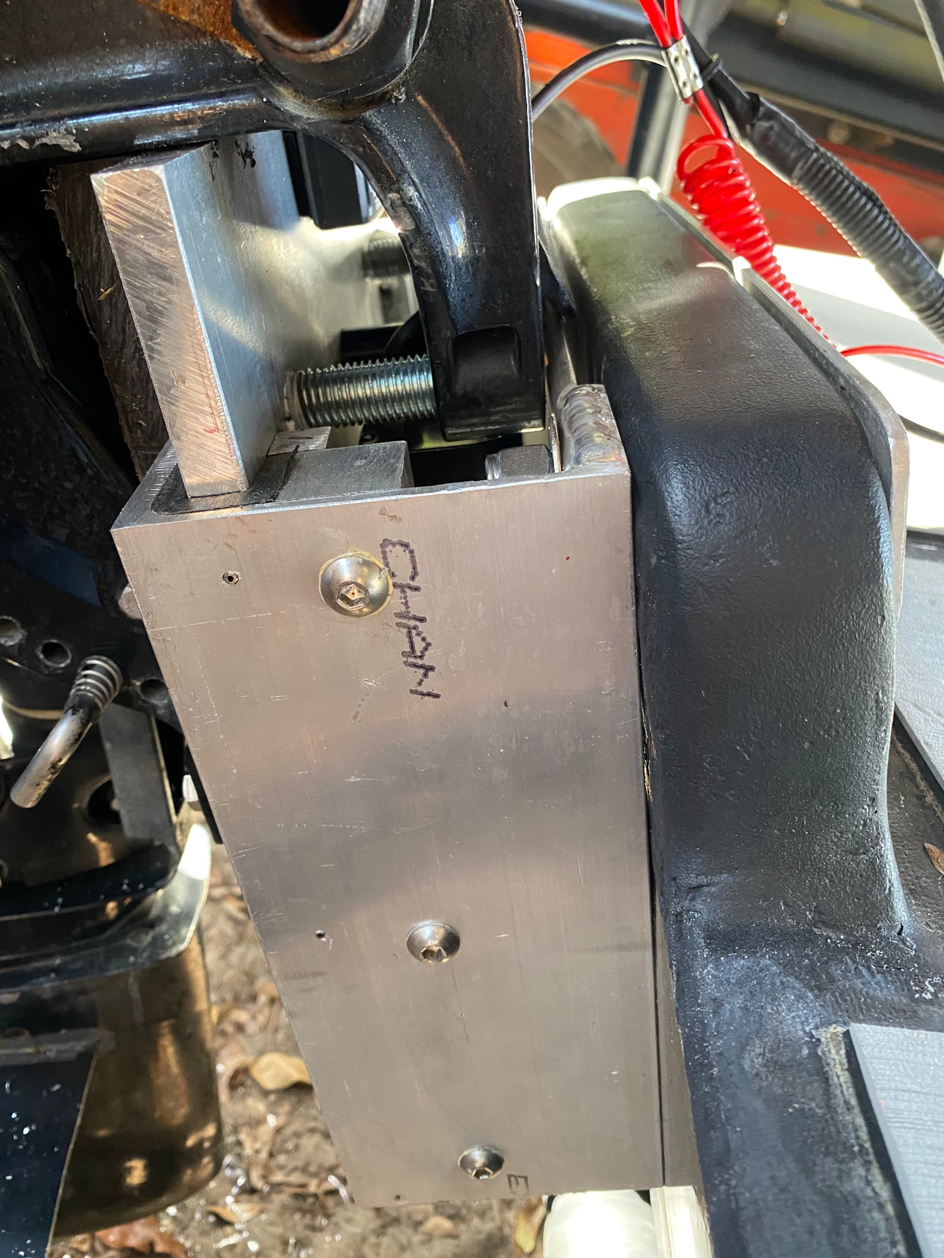
Here you can see I had to shorten the clamp screws. I just picked up some stainless threaded rod and cut it to length. To avoid this, 6” channel as opposed to 4” would give plenty of clearance.
Final weight I believe was 18lbs.